One convenient feature of Chromecast is that it turns on your TV automatically when you connect to it - as long as your TV has HDMI-CEC. Mine doesn’t, but it is already remote-controlled via Raspberry Pi, and thanks to Home Assistant, I can easily detect when the Chromecast is in use, so in theory I could just blast a command to the IR when it switches away from “off”.
There is just one problem: Home Assistant doesn’t know whether the TV is on or off. If it is already on when I start casting, sending the command will turn it off - the opposite of what I want. Also, I would like to turn the TV off when not using the Chromecast (something it doesn’t seem to do, even with HDMI-CEC).
Detecting power via USB
I am not the only one: people have already asked around, and one of the ideas was to use the USB port (that a lot of sets have for playing media or firmware upgrades). A quick multimeter test on mine showed that it is only powered when the TV is on, so it’s just a question of monitoring it and forwarding the info to Home Assistant.
Attempt 1: Raspberry Pi GPIO (spoiler: 👍 for polling, 👎 for Home Assistant)
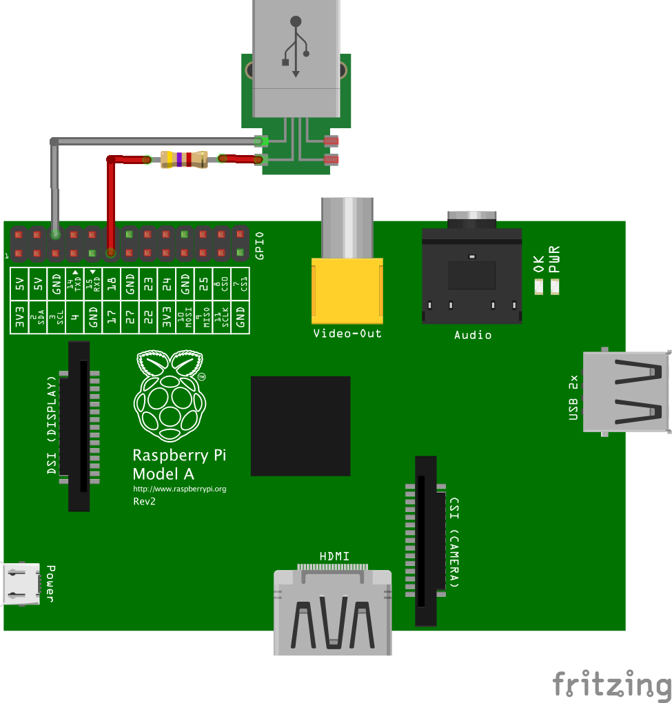
The simplest idea for monitoring the state would be to connect the power output of the TV to a GPIO pin on the Raspberry Pi. However, those pins expect 3.3V, and USB operates at 5V, so a direct connection would fry the RPi. I knew I’d need what is known as a “voltage divider” - a setup that (in its simplest form) uses two resistors to extract a lower voltage from a higher one.
The good news: someone had already done the homework for me, noticing the Rasperry Pi already provides one of the resistors and calculating the value of the other. So it was as simple as:
- Connecting the TV USB GND to a Pi GND pin (e.g., pin 9);
- Connecting the TV USB 5V to a 4.7kΩ resistor, and the resistor to a Pi GPIO pin (e.g., GPIO17, which is pin 11 on the board);
- Software-enable the pull-down resistor on that pin and read it to know if the TV is on or off.
You can reuse any cable with a USB connector - they are usually color-coded, red being the 5v, and the silver, non-isolated wire is GND. Raspberry Pi pinout is here, but here is my wiring for this setup:
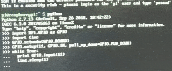
To test it, we can invoke python2 and type some Python code:
import RPi.GPIO as GPIO
import time
GPIO.setmode(GPIO.BOARD)
GPIO.setup(11, GPIO.IN, pull_up_down=GPIO.PUD_DOWN)
while True:
  print GPIO.input(11)
  time.sleep(1)
This prints 1 when the TV is off and 0 when it is off. Here is a test I did plugging and unplugging the USB to a power adaptor:
On the actual TV, it takes some time to pick up the “off” state because the TV slowly reduces the output instead of cutting it straight (I checked with a multimeter, it takes quite a few seconds to go from ~5V to ~0).
Anyway, it shows that the hardware works, so we can move on to exposing it in Home Assistant. It will appear on the panel as a binary_sensor just by adding these lines to the binary_sensor section of configuration.yaml (creating one if you don’t have it):
binary_sensor:
  - platform: rpi_gpio
    ports:
      17: PIR TV # rpi_gpio uses BCM notation => physical pin 11 = GPIO17
    pull_mode: DOWN
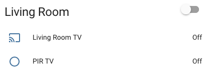
And it almost works 🥺. Even though the sensor shows up on the interface (alongside the Chromecast, on the screenshot), and switches to on when I turn the TV on, it does not switch to off when I turn the TV off. Never.
It happens that (unsurprisingly), Home Assistant code is more efficient than mine, using threaded callbacks instead of checking the state every second (details).
So I changed my test code to match Home Assistant’s:
import RPi.GPIO as GPIO
GPIO.setmode(GPIO.BOARD)
GPIO.setup(11, GPIO.IN, pull_up_down=GPIO.PUD_DOWN)
def cb(port):
  print GPIO.input(port)
GPIO.add_event_detect(11, GPIO.BOTH, callback=cb, bouncetime=1000)
Instead of continuously printing, it will just output the current state when it changes, and works as expected fine when plugging/unplugging from the power adaptor.
When connected to the TV, turning it of produces a “1”, but turning it off also produces a “1”. It isn’t a bounce issue (I tried changing bouncetime to no avail).
My other guess is that the state returned by GPIO.input isn’t updated when the cb function is fired by the callback, likely due to the slow discharge. To confirm that, I include a little pause (200ms) on the function before I read the state, and, lo and behold, that fixes the problem. The code above consistently prints “0” when I turn the TV off:
import RPi.GPIO as GPIO
import time
GPIO.setmode(GPIO.BOARD)
GPIO.setup(11, GPIO.IN, pull_up_down=GPIO.PUD_DOWN)
def cb(port):
  time.sleep(0.2) # Pause for 200ms
  print GPIO.input(port)
GPIO.add_event_detect(11, GPIO.BOTH, callback=cb, bouncetime=1000)
I could change the Home Assistant code on the Pi to do that (maybe accepting an optional delay parameter in the same way that it accepts a bounce time), but I had a hard time running their tests, so it will be a while before I can submit a contribution to the project (which may or may not be accepted), so for now I went with ha different approach:
Attempt 2: Arduino (NodeMcu ESP8266) GPIO (👍)
To be honest, I haven’t been using the Raspberry Pi GPIO for a while precisely because of this type of issue: running I/O on a non-realtime (or at least not very predictable OS) leads to inconsistent reads. Instead, I’ve switched all the I/O on my home automation to a separate board (a NodeMcu Lua ESP8266, which behaves like an Arduino, but is more compact and has built-in Wi-Fi).
The board runs OpenMQTTGateway, a software that makes it easy to forward hardware events to the Raspberry Pi (here is how I set it up to work with Home Assistant) and brings us the best of two worlds: the stability of the microcontroller and the software flexibility of the Pi.
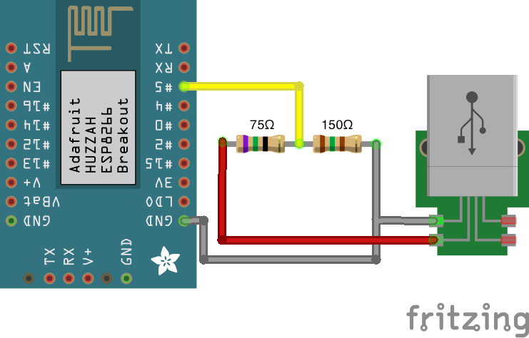
For this setup, we don’t have the Rapsberry-pi-provided pull-down, so we’ll need two resistors to provide the voltage divider (i.e., bring the TV USB 5v down to 3.3v that the board can monitor).
There is a formula that you can use to find a pair of resistors, but I was lazy and just used this calculator, throwing 5V as the voltage input and playing with values until I got a pair that I had lying around (R1 = 75Ω and R2 = 150Ω) and gave an approximate 3.3v output.
Here is how I wired them (you must choose a pin you are not using for some other I/O):
Opening OpenMQTTGateway’s source code in the Arduino IDE, I enabled the monitoring by removing the trailing // from this line in User_config.h:
#define ZsensorGPIOInput "GPIOInput" //ESP8266, Arduino, ESP32
and in config_GPIOInput.h, I configured the pin I’m using by adding it to the first #define on the block below PIN_DEFINITIONS (the correct number depends on your board). In the one depicted above, D5 means GPIO14, so we’d go with:
#if defined(ESP8266) || defined(ESP32)
  #define GPIOInput_PIN 14
#else
  #define GPIOInput_PIN 7
#endif
Of course there are other configurations you may want to change to ensure the software connects to your Wi-Fi network, and that the Raspberry Pi can subscribe to the events published by OpenMQTTGateway (see the docs and my previous post).
Once everything is set up, it is possible to ssh into the Raspberry Pi and monitor the queue with:
mosquitto_sub -t \# -v
As the TV is turned on and off, the following events appear:
home/OpenMQTTGateway/GPIOInputtoMQTT {"gpio":"HIGH"}
home/OpenMQTTGateway/GPIOInputtoMQTT {"gpio":"LOW"}
That allowed me to add a binary_sensor to Home Assistant’s configuration.yaml. Like I did with the sensors in the aforementioned post, I used the mqtt platform, telling it to watch for the messages above:
binary_sensor:
  - platform: mqtt
    name: Living Room TV Power
    state_topic: "home/OpenMQTTGateway/GPIOInputtoMQTT"
    payload_on: '{"gpio":"HIGH"}'
    payload_off: '{"gpio":"LOW"}'
    device_class: power
That makes the switch appear, and this time it reacts to on and off!
Using the power state as a condition to toggle TV state when Chromecast plays/stops
The final goal is to to monitor my Chromecast (media_player.living_room_tv)’s state. When it changes from off to anything else, I want it to send a power toggle command to my TV (which I defined as the switch.tv when I set up IR) - but only if the sensor we just installed says the TV is off.
In Home Assistant language, that translates to these lines in automations.yaml:
- alias: tv_on_when_start_casting
  trigger:
    platform: state
    entity_id: media_player.living_room_tv
    from: 'off'
  condition:
    condition: state
    entity_id: binary_sensor.living_room_tv_power
    state: 'off'
  action:
  - service: switch.toggle
    entity_id: switch.tv
Conversely, if I want it to turn off the TV when I’m done with the Chromecast (and again, only if I haven’t turned it off already):
- alias: tv_off_when_stop_casting
  trigger:
    platform: state
    entity_id: media_player.living_room_tv
    to: 'off'
  condition:
    condition: state
    entity_id: binary_sensor.living_room_tv_power
    state: 'on'
  action:
  - service: switch.toggle
    entity_id: switch.tv
A few quirks still remain. For example, if I switch sources without giving the setup a few seconds to catch up, the TV will turn off, but not on again. Worse: if I switch to another HDMI source without disconnecting, the Chromecast will become idle after a while, and turn the TV off at the worst possible moment.
But those are likely fixable by tweaking the automations, and in general I just start casting and everything works!